
Views: 0 Author: Site Editor Publish Time: 2026-08-12 Origin: Site


NMC pouch cells combine high energy density with a lightweight, space-efficient format, making them suitable for electric vehicles, drones, robots, industrial equipment, marine systems and custom battery packs.
However, NMC describes the cathode chemistry, while “pouch” describes the cell format. Neither term alone determines the correct voltage limits. Nominal voltage, maximum charge voltage, discharge cut-off voltage, current limits and temperature limits must always be confirmed from the approved datasheet for the selected cell.
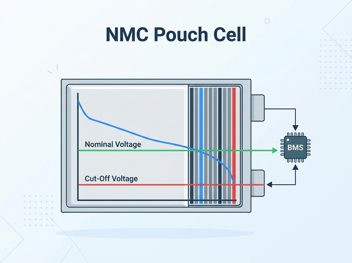
For many conventional NMC/graphite cells, the nominal voltage is approximately 3.6V to 3.7V, the charge-voltage target is commonly 4.20V, and the specified end-of-discharge voltage is often somewhere between 2.5V and 3.0V. These are typical values—not universal settings for every NMC pouch cell.
A typical NMC pouch cell has a nominal voltage of approximately 3.6V to 3.7V.
Many standard NMC/graphite cells use a 4.20V CC/CV charging profile, but the exact limit must come from the cell datasheet.
The specified discharge cut-off commonly falls between 2.5V and 3.0V, depending on the cell design and test conditions.
BMS protection thresholds are emergency protection limits, not normal operating targets.
Cell voltage under load is lower than open-circuit voltage because of internal and connection resistance.
Voltage alone is not sufficient for accurate State of Charge estimation during operation.
Lowering the upper charging voltage or narrowing the operating SOC window may improve service life, but the result is cell- and application-specific.
The following values are useful for preliminary system planning, but they should not replace the manufacturer’s datasheet.
| Parameter | Typical Reference Range | Engineering Use |
|---|---|---|
| Nominal voltage | 3.6V–3.7V | Pack voltage and preliminary energy calculations |
| Charge-voltage target | Commonly 4.20V | Charger CC/CV setting |
| End-of-discharge voltage | Commonly 2.5V–3.0V | Capacity test and lower operating limit |
| High-cell warning | Application-specific | Charge-current reduction or user warning |
| Cell overvoltage protection | Datasheet- and tolerance-based | Emergency charge disconnection |
| Low-cell warning | Application-specific | Power derating or low-battery warning |
| Cell undervoltage protection | Datasheet- and load-based | Emergency discharge disconnection |
Some NMC cells use voltage limits outside these typical values. High-voltage cell designs, power cells and energy cells may have different requirements even when they share the same nominal capacity.
Nominal voltage is a representative average operating voltage used for cell identification, pack calculations and energy estimation. It is not the voltage that the cell maintains throughout the complete discharge cycle.
A fully charged conventional NMC cell may begin near 4.20V and then gradually decline as energy is removed. The measured voltage is affected by:
State of Charge
Charge or discharge current
Cell temperature
Cell resistance
Cell age and State of Health
Rest time after charging or discharging
For a preliminary energy calculation:
Cell energy (Wh) ≈ nominal voltage (V) × capacity (Ah)
For example, a 76Ah cell rated at 3.7V has an estimated nominal energy of:
3.7V × 76Ah = 281.2Wh
This is a nominal calculation. Actual usable energy depends on the complete voltage curve, current, temperature and the system’s upper and lower voltage limits.
Cells connected in series increase voltage. Cells connected in parallel increase capacity and current capability.
If a cell datasheet specifies:
Nominal voltage: 3.7V
Charge-voltage limit: 4.20V
End-of-discharge voltage: 2.75V
A 14S pack would have:
Nominal pack voltage: 14 × 3.7V = 51.8V
Maximum charge voltage: 14 × 4.20V = 58.8V
Datasheet-based end-of-discharge voltage: 14 × 2.75V = 38.5V
The final equipment must operate correctly across the complete pack-voltage range—not only at the advertised nominal voltage.
Motor controllers, inverters, DC/DC converters, contactors, fuses, capacitors and pre-charge circuits should all be checked against the maximum pack voltage. The lower operating limit should also account for voltage sag during peak-current demand.
Many conventional NMC pouch cells use a 4.20V constant-current/constant-voltage charging profile.
During the constant-current stage, the charger supplies the permitted charging current while cell voltage rises. When the pack reaches the charger’s voltage target, charging enters the constant-voltage stage.
During the constant-voltage stage, the charger holds the target voltage while the charging current gradually decreases. Charging should terminate when the current reaches the value specified by the cell manufacturer or when another approved termination condition is met.
The exact charging profile must define:
Maximum charging current
Maximum cell and pack voltage
Constant-voltage target
Charge-termination current
Maximum charging time
Permitted charging-temperature range
Recharge or recovery conditions
The BMS should not be used as the normal charge controller. The charger must regulate voltage and current correctly, while the BMS provides independent protection if the charger or system control fails.
No.
A 4.20V charge target is common for many NMC/graphite cells, but it is not universal. Different electrode formulations and cell designs may use different maximum charging voltages.
The BMS overvoltage threshold must be selected from the approved cell specification and coordinated with:
Charger voltage tolerance
BMS voltage-measurement accuracy
Wiring and sensing error
Detection delay
Cell imbalance
Temperature
Required safety margin
Publishing one universal value—such as setting every NMC BMS to 4.25V—is not recommended. A value that is acceptable for one cell may exceed the permitted voltage of another.
The end-of-discharge voltage is the lower voltage used by the manufacturer when measuring rated capacity under defined test conditions.
For NMC cells, this value is commonly between approximately 2.5V and 3.0V, but the exact number may vary with cell design. It should not automatically become the normal daily operating target.
Operating close to the datasheet minimum may provide slightly more measured capacity, but it can also result in:
Greater voltage sag under load
Earlier low-voltage shutdown at cold temperatures
Reduced power near the end of discharge
Increased sensitivity to cell imbalance
Higher risk of overdischarging the weakest series cell
Possible reduction in service life
Sustained or severe overdischarge can damage the electrodes and the solid-electrolyte interphase. In a series-connected pack, continued current after one weak cell is depleted can drive that cell into reversal. Under severe overdischarge conditions, copper-current-collector dissolution and internal short-circuit mechanisms may occur.
The BMS should therefore disconnect the load before a cell remains beyond its permitted lower limit.
Cell voltage measured under load is lower than the cell’s relaxed open-circuit voltage. This difference is commonly called voltage sag.
A simplified estimate is:
Voltage sag ≈ current × resistance
If a cell has a DC resistance of 2mΩ and the current is 100A:
ΔV = 100A × 0.002Ω = 0.20V
However, real pack resistance also includes:
Cell tabs
Busbars
Welded or bolted joints
Fuses and contactors
Cables and connectors
Parallel-group current distribution
Resistance also changes with temperature, State of Charge and aging. A cold or aged cell may therefore experience more voltage sag than a new cell tested at room temperature.
The BMS must distinguish between a short transient sag and a genuinely depleted cell. This is why undervoltage protection normally includes a validated detection delay and recovery hysteresis.
There is no universal safe delay. It must be verified using the actual cell, load profile, minimum operating temperature and worst-case pack resistance.
Open-circuit voltage is the cell voltage measured after the charge or discharge current has stopped and the cell has had enough time to relax.
Immediately after charging, voltage may remain higher than its fully relaxed value. After a heavy discharge, voltage may recover upward once the load is removed. The required relaxation time depends on the cell, temperature and the accuracy required by the estimation method.
An OCV–SoC table should therefore be generated or supplied for the specific cell. A generic table cannot accurately represent every NMC formulation.
During operation, a robust BMS normally combines:
Coulomb counting
Cell-voltage measurement
Temperature compensation
OCV correction during suitable rest periods
Capacity and State of Health estimation
Resistance or model-based correction
Coulomb counting is useful, but current-sensor offset and capacity-estimation errors accumulate over time. Periodic correction is required to prevent SoC drift.
The following table describes the configuration logic. It intentionally does not provide universal voltage values.
| BMS Parameter | Recommended Basis |
|---|---|
| High-cell warning | Set below the protection trip point to allow the charger or controller to reduce current |
| Cell overvoltage protection | Coordinate with the cell’s permitted maximum voltage and all measurement and charger tolerances |
| Overvoltage release | Set below the trip threshold with suitable hysteresis |
| Low-cell warning | Set high enough to provide useful warning or power derating before disconnection |
| Cell undervoltage protection | Protect the cell before a sustained violation of its approved lower limit |
| Undervoltage delay | Validate against transient voltage sag and the application’s peak-load duration |
| Undervoltage release | Define safe recovery and recharge behavior |
| Balancing start voltage | Select from the cell’s upper-SOC voltage behavior and the charging strategy |
| Balance differential | Base on measurement accuracy, cell matching and required pack performance |
| Charge temperature limits | Follow the cell datasheet and validated charge-current derating map |
| Discharge temperature limits | Follow the cell datasheet and system thermal design |
The protection configuration should also define fault logging, recovery conditions, charger communication, contactor behavior and whether a fault requires automatic or manual reset.
In a series-connected battery pack, the cell or parallel group with the lowest usable capacity limits the energy of the entire pack.
Passive balancing removes a small amount of energy from higher-voltage cells through resistors. Active balancing transfers energy between cells or groups and may be useful in large packs or systems with higher imbalance.
Balance-current selection must be related to cell capacity.
For example, a 1% capacity difference in a 76Ah cell equals:
76Ah × 1% = 0.76Ah
With a 100mA passive balancing current, the ideal balancing time would be:
0.76Ah ÷ 0.10A = 7.6 hours
Actual time will be longer because balancing may operate only during part of the charge cycle and may be limited by temperature, duty cycle or BMS measurement scheduling.
Balancing near the upper part of the SOC range is often useful for NMC because voltage differences become easier to interpret. However, a universal “start balancing above 4.0V” rule should not be applied without reviewing the cell’s OCV curve and the pack’s charging strategy.
Good cell matching before assembly remains important. A small balancing circuit cannot quickly correct a large capacity or resistance mismatch in a high-capacity pouch-cell pack.
NMC charge and discharge limits depend strongly on temperature.
Charging a conventional graphite-anode lithium-ion cell at low temperature can increase the risk of lithium plating, especially at high charging current. Many cells do not permit charging below 0°C, while some allow only a reduced current within a specified low-temperature range.
The BMS should implement the exact temperature limits and current-derating map supplied by the cell manufacturer.
Temperature-sensor placement should reflect the module design. Sensors may be required on representative cell surfaces, tabs, busbars or known thermal hot spots. The best location depends on whether the primary concern is cell-core temperature, tab heating, connection resistance or cooling-system performance.
The thermal design should be validated under:
Maximum continuous charge
Maximum continuous discharge
Peak-current operation
Low-temperature charging
High-temperature operation
Cooling-system failure
Cell-to-cell temperature variation
Reducing time at very high SOC and avoiding unnecessary deep discharge can often improve NMC battery life. Lowering the upper charge voltage may also reduce degradation, but the capacity and life-cycle trade-off must be measured for the selected cell.
It is not accurate to promise that charging to one specific voltage will always double or triple cycle life.
Battery aging is also affected by:
Cell temperature
Charge and discharge rate
Depth of discharge
Average SOC
Storage SOC
Time spent at maximum voltage
Mechanical pressure
Cell matching
Cooling uniformity
For applications that do not require maximum energy on every cycle, the engineering team can evaluate a narrower SOC window. The final setting should be based on cycle testing and the customer’s warranty and runtime targets.
Pouch cells require more than correct electrical settings. Their laminated enclosure does not provide the same structural support as a rigid cylindrical or prismatic metal case.
A complete module design should consider:
Manufacturer-specified compression or restraint
Cell expansion throughout life
Insulation around tabs and edges
Protection against puncture and abrasion
Busbar flexibility and tab strain
Cooling contact and temperature uniformity
Allowance for manufacturing tolerances
Detection of abnormal swelling
Swelling can be associated with aging, high temperature, overcharge or other abnormal conditions. Compression must not be used to hide an electrically or chemically damaged cell.
If a project uses the Farasis P76D or another large-format 76Ah NMC pouch cell, the engineering process should begin with the current manufacturer-approved datasheet for the exact cell revision and production batch.
Confirm at least:
Nominal voltage and capacity
Maximum charge voltage
Recommended and absolute discharge limits
Standard and maximum charge current
Continuous and pulse discharge current
DC internal resistance
Temperature limits
Cell dimensions and swelling allowance
Compression requirements
Cycle-life test conditions
If the approved specification lists 3.7V nominal voltage, 4.20V maximum charge voltage and 2.75V end-of-discharge voltage, these values can be used for pack calculations. The BMS thresholds should then be developed with suitable margins and verified through pack-level testing.
Generic NMC settings should never be copied directly into production firmware without this validation.
Before releasing an NMC pouch-cell battery pack, verify the following:
Confirm the current cell datasheet and specification revision.
Calculate nominal, maximum and minimum pack voltage from the exact series count.
Confirm compatibility with the inverter, motor controller, charger and DC/DC converter.
Program charger voltage, current and termination conditions.
Configure BMS warnings, protection thresholds, delays, hysteresis and recovery logic.
Include BMS and charger measurement tolerances in the protection analysis.
Validate voltage sag at maximum current, low SOC and minimum operating temperature.
Verify temperature-sensor placement and thermal cut-offs.
Confirm balancing current is suitable for the cell capacity and expected mismatch.
Calibrate SoC estimation across temperature and aging conditions.
Test open-wire, overcurrent, short-circuit, overvoltage and undervoltage protection.
Validate mechanical restraint, insulation, tab support and cooling.
Record cell traceability and pack-level test data.
Most conventional NMC pouch cells are rated at approximately 3.6V or 3.7V nominal. The exact value depends on the manufacturer’s test method and cell design.
Many standard NMC/graphite cells use 4.20V as the charging target. Some cell designs use a different value, so the approved datasheet must be checked.
Depending on the cell, the specified end-of-discharge voltage is commonly between approximately 2.5V and 3.0V. The normal system cut-off may be set higher to improve power availability, cold-temperature performance or service life.
No. The overvoltage threshold must be coordinated with the selected cell’s permitted maximum voltage, the charger tolerance, BMS accuracy and protection response time.
The current flowing through the cell and pack resistance produces an instantaneous voltage drop. Cold temperature, low SOC, aging and connection resistance can increase this sag.
Not during active operation. Accurate SoC estimation normally combines coulomb counting, voltage, temperature, cell models and periodic OCV correction.
No. The charger must provide the correct CC/CV profile and charge termination. The BMS monitors the cells and provides independent protection against abnormal conditions.
NMC pouch-cell voltage management should begin with the selected cell’s approved datasheet—not a universal set of internet values.
Values such as 3.6V to 3.7V nominal voltage, 4.20V charging voltage and 2.5V to 3.0V end-of-discharge voltage are useful reference points, but they do not automatically define the correct settings for every NMC pouch cell.
A reliable battery pack coordinates cell specifications, charger control, BMS protection, temperature management, voltage-sag testing, cell balancing and pouch-cell mechanical support.
Misen supplies NMC pouch cells and supports cell selection, specification review, BMS matching and custom battery-module development. Send us your required pack voltage, capacity, continuous and peak current, operating temperature and available installation dimensions to begin the cell-selection process.
The high energy density and form factor flexibility of the NMC pouch cell make it a premier choice for electric vehicles and high-drain applications. These advantages demand uncompromising precision in voltage management. Misinterpreting voltage specifications leads to severe consequences on the shop floor and in the field. Ignoring voltage sag under heavy load triggers false system shutdowns. Misunderstanding resting voltage causes inaccurate capacity readings. Misconfiguring cut-off thresholds leads to accelerated cell degradation, mechanical swelling, or catastrophic thermal runaway.
To transition from cell selection to safe pack assembly, engineering teams must align nominal, peak, and cut-off voltages with exact Battery Management System (BMS) parameters. This guide breaks down the critical voltage thresholds, dynamic behaviors, and BMS configurations required for reliable deployment. You will learn how to set precise protection limits, interpret dynamic load behaviors accurately, and configure charging profiles that balance maximum capacity with long-term reliability.
Strict Voltage Boundaries: Standard NMC chemistry operates safely within a rigid 2.5V (absolute minimum) to 4.2V (absolute maximum) window; exceeding these limits causes irreversible chemical degradation.
Dynamic Load Considerations: Voltage sag during Wide Open Throttle (WOT) or high-current draw must be factored into BMS under-voltage protection to prevent nuisance tripping while maintaining cell safety.
Resting vs. Active Voltage: Terminal voltage will read artificially high immediately after charging (surface charge) and requires a settling period to reflect true Open Circuit Voltage (OCV).
BMS is Non-Negotiable: A properly configured BMS utilizing Constant Current/Constant Voltage (CC/CV) profiles and precise Over-Voltage/Under-Voltage Protection (OVP/UVP) is mandatory for lifecycle optimization and safety compliance across all lithium chemistries.
Trade-offs in Cycle Life: Limiting the maximum charge voltage to 4.05V–4.1V instead of the 4.2V maximum can exponentially increase the cycle life of an NMC pouch cell, sacrificing minor top-end capacity for long-term reliability.
Nominal voltage represents the average operating voltage during a standard discharge cycle. For standard NMC (Nickel Manganese Cobalt) chemistry, this value typically sits between 3.6V and 3.7V. We determine this figure by discharging a fully charged cell at a moderate rate, usually 0.2C to 0.5C, and calculating the median voltage over the entire discharge curve. This metric serves as the foundational baseline for all energy calculations on the bench.
You use the nominal voltage to calculate total pack energy in Watt-hours (Wh). Multiplying the nominal voltage by the cell's Ampere-hour (Ah) capacity yields the total energy. When building battery packs, you scale this nominal voltage by connecting cells in series (S) and parallel (P). The math dictates the final system architecture and component selection.
Let's look at how this scales to the pack level. A 14S (14 cells in series) configuration yields a nominal voltage of approximately 50.4V (14 x 3.6V). Fully charged, this pack reaches 58.8V (14 x 4.2V). A 16S configuration pushes the nominal voltage to 57.6V, with a maximum charge voltage of 67.2V. You must design motor controllers, inverters, and pre-charge circuits to handle this entire voltage sweep, not just the nominal rating. If you size your contactors based only on the 50.4V nominal figure, you risk welding the contacts shut when the pack is fully charged at 58.8V.
The absolute maximum terminal voltage for a standard NMC cell is 4.20V. Manufacturing tolerances generally allow a strict variance of ± 0.05V per cell. Pushing voltage beyond this hard limit triggers immediate and irreversible chemical breakdown within the cell architecture. You cannot rely on the charger's display alone; you must verify terminal voltage at the cell tabs using a calibrated multimeter during the initial pack balancing phase.
Surface charge creates a temporary resting voltage phenomenon. Immediately after completing a charge cycle, the terminal voltage reads artificially high. The internal chemistry requires a settling period, often several hours, to reach equilibrium. Only after this resting phase will a multimeter reflect the true Open Circuit Voltage (OCV). Calibrating your BMS based on immediate post-charge voltage leads to inaccurate State of Charge (SoC) estimations and premature balancing triggers.
Overcharging carries severe implementation risks. Exceeding 4.2V causes lithium plating on the anode. The electrolyte begins to oxidize, generating gas. Because pouch cells lack a rigid cylindrical casing, this gas generation leads directly to mechanical swelling. Swollen cells exert pressure on adjacent cells, compromising the structural integrity of the entire module and potentially rupturing the aluminum laminate pouch.
Engineers face a distinct evaluation dimension regarding maximum charge limits. Charging to a full 4.2V extracts 100% of the rated capacity but stresses the internal chemistry. Limiting the charge to 4.0V or 4.1V captures roughly 80% to 90% of the capacity. This slight reduction in range drastically reduces mechanical stress and extends the overall cycle life of the pack. For stationary storage applications, this trade-off is almost always worth making.
The discharge cut-off voltage marks the absolute lower limit of operation. At this threshold, the cell is considered fully depleted, reaching 0% State of Charge. For NMC chemistry, manufacturers typically define this limit between 2.5V and 2.8V under load. Extracting energy below this point provides negligible additional runtime but introduces massive chemical risks.
The discharge curve features a distinct "knee" around 3.2V. Below this point, the voltage drops off a cliff. There is virtually no usable energy left between 3.0V and 2.5V. Pushing the cell into this deep discharge zone is dangerous and counterproductive.
Deep discharging below 2.5V initiates copper dissolution. The copper current collector on the anode begins to break down and dissolve into the electrolyte. When you subsequently recharge the cell, these dissolved copper ions precipitate out. They form metallic dendrites that pierce the separator.
This creates internal short circuits. A cell damaged by deep discharge may appear to function normally for several cycles before suddenly failing. Permanent capacity loss is guaranteed. To prevent this, system designers must enforce strict low-voltage cut-offs at both the hardware and software levels, ensuring the BMS physically disconnects the load before the cells reach this critical threshold.
Internal resistance (IR) causes a phenomenon known as voltage sag during high-current discharge events. When an electric vehicle operator demands Wide Open Throttle (WOT), the motor pulls massive amperage from the battery pack. According to Ohm's Law, this high current multiplying against the cell's internal resistance results in an immediate voltage drop at the terminals.
You must quantify acceptable sag to design a robust system. Let's look at a practical calculation. If a cell has 2 milliohms (0.002 ohms) of internal resistance and you pull 100 amps, the voltage sag is V = I * R = 100 * 0.002 = 0.2V. During a WOT event, a temporary drop of 0.2V to 0.4V per cell is entirely typical. The exact magnitude depends heavily on the specific C-rate demanded and the DC internal resistance (DCIR) of the cell. High-performance cells with thicker tabs and optimized chemistry exhibit less sag.
This creates a complex problem framing for BMS programming. The system must differentiate between a genuinely depleted cell and a temporary voltage drop under heavy load. If the BMS relies on a hard, instantaneous voltage cut-off, a WOT event at 30% SoC might drag the terminal voltage below 2.8V. This triggers a premature and dangerous system shutdown while driving. You must implement time-delayed protection thresholds to manage this dynamic behavior.
NMC chemistry exhibits a distinct, non-linear discharge curve. This wide, sloped curve contrasts sharply with the extremely flat discharge profile of LiFePO4 batteries. The sloped nature of the NMC curve makes it somewhat easier to estimate remaining capacity based on voltage alone, but only under strict resting conditions.
The curve features a long plateau region between approximately 3.9V and 3.4V. Within this window, the voltage drops slowly and steadily as the cell discharges. At the top end (4.2V to 3.9V) and the bottom end (3.4V to 2.8V), the voltage drop-off is steep and rapid. This non-linear behavior complicates real-time capacity tracking.
| Approximate State of Charge (SoC) | Resting Open Circuit Voltage (OCV) | Discharge Curve Phase |
|---|---|---|
| 100% | 4.20V | Steep Drop |
| 80% | 3.95V | Entering Plateau |
| 50% | 3.70V | Mid-Plateau (Nominal) |
| 20% | 3.45V | Exiting Plateau |
| 0% | 2.80V - 3.00V | Steep Drop (Cut-off) |
Relying solely on voltage for SoC estimation remains insufficient for active NMC cells. Because voltage sags under load and rebounds during rest, a simple voltage lookup table will display wild fluctuations during operation. You must utilize coulomb counting within the BMS. Coulomb counting measures the exact current flowing in and out of the pack, integrating this data over time to provide a highly accurate, stable SoC percentage.
Analyzing the Farasis P76D pouch cell specifications provides a clear benchmark for high-capacity NMC technology. This specific cell delivers a substantial 76Ah capacity, making it ideal for energy-dense module designs. The voltage parameters align with top-tier NMC chemistry standards.
The nominal voltage sits at 3.7V, indicating a robust plateau region during discharge. The recommended charge limit is strictly capped at 4.2V, while the standard discharge cut-off is set at 2.75V. These ratings yield exceptional energy density metrics, allowing engineers to pack maximum kilowatt-hours into restricted physical footprints. The wide tabs on these cells are specifically designed to handle high continuous discharge currents while minimizing localized heating.
The thermal characteristics and discharge capabilities of the Farasis P76D align perfectly with success criteria in EV drivetrains and demanding energy storage applications. High capacity per cell reduces the number of parallel connections required in a pack. This simplifies the busbar architecture, reduces the number of required laser welds, and eliminates potential points of failure.
However, utilizing large-format pouch cells introduces specific mechanical constraints. Pouch cells naturally expand and contract during normal charge and discharge cycles. You must implement engineered compression plates and foam pads within the module housing. Proper mechanical compression manages this normal expansion, prevents delamination of the internal layers, and maintains optimal contact between the electrodes and the separator. Without adequate compression, the internal resistance will steadily climb as the cell ages.
Defining exact BMS setpoints is a critical solution approach for NMC chemistry. You cannot rely on default factory settings; you must tailor the thresholds to the specific cell data sheet. Proper configuration utilizes a tiered approach, utilizing both alert levels and hard disconnect levels.
OVP Alert Threshold: Set to ~4.15V. The BMS triggers a warning and may initiate balancing or request a charge current reduction from the charger via CAN bus.
OVP Disconnect Threshold: Set strictly at 4.25V. The BMS opens the contactor, physically severing the charge current to prevent catastrophic overcharging.
UVP Alert Threshold: Set to ~3.0V. The system warns the user of low capacity and may restrict motor torque to limit current draw.
UVP Disconnect Threshold: Set between 2.7V and 2.8V. The BMS completely shuts down the discharge path to prevent copper dissolution.
You must configure delay timers for these UVP settings. A typical delay of 2 to 5 seconds prevents transient voltage sag during WOT events from triggering a nuisance disconnect. If the voltage drops below 2.7V for only 500 milliseconds during hard acceleration, the timer prevents a shutdown. If the voltage remains below 2.7V for a full 3 seconds, the BMS recognizes a genuinely depleted cell and opens the contactor.
Cell balancing ensures all cells within a series string reach their maximum charge simultaneously. Without balancing, the cell with the lowest capacity dictates the usable energy of the entire pack. You must choose between active and passive balancing strategies based on pack size and application.
Passive balancing bleeds excess voltage from the highest-charged cells by routing current through bypass resistors, dissipating the energy as heat. For well-matched, high-quality NMC pouch cells, passive balancing is typically sufficient. The balancing current is usually small, ranging from 50mA to 200mA. Keep in mind that a 50mA bleed resistor will take days to balance a severely out-of-balance 76Ah cell, which is why initial top-balancing on the bench is critical before final pack assembly.
The BMS must initiate passive balancing only near the very top of the charge cycle, typically above 4.0V per cell. Attempting to balance cells during the flat portion of the discharge curve (around 3.6V) is highly risky. Because the voltage differences in the plateau region are minimal, the BMS may misinterpret slight variations in internal resistance as capacity imbalances, leading to incorrect and counterproductive balancing actions.
Voltage thresholds are not static; they must be dynamically adjusted based on ambient and internal cell temperatures. A robust BMS utilizes multiple thermistors placed directly against the cell tabs and pouch bodies to monitor real-time thermal data. Placing thermistors on the busbars provides the fastest response time for detecting high-current heating.
Charging NMC cells at or below freezing (0°C) presents a severe implementation risk. At low temperatures, the intercalation of lithium ions into the graphite anode slows down drastically. If you apply standard charge currents at freezing temperatures, the lithium ions cannot penetrate the anode fast enough. They accumulate on the surface, causing permanent lithium plating.
To prevent this, the BMS must enforce strict thermal limits. Below 5°C, the BMS should severely derate the allowable charge current. At or below 0°C, the BMS must completely disable charge current while still allowing low-rate discharge. High-temperature cut-offs are equally critical; charge and discharge should be disabled if cell temperatures exceed 60°C to prevent thermal runaway. Active liquid cooling systems should be integrated with the BMS to maintain the pack within the optimal 20°C to 35°C window.
High-tier NMC packs require a strict Constant Current / Constant Voltage (CC/CV) charging profile. This two-stage process ensures safe, complete charging without exceeding maximum voltage thresholds. You must program your charging hardware to follow this exact sequence.
During the Bulk Stage (CC), the charger delivers a constant, maximum allowable current to the battery pack. The voltage steadily rises as the pack absorbs energy. This stage continues until the highest cell in the pack reaches the target absorb voltage, typically 4.2V. The CC phase delivers roughly 80% to 90% of the total charge. Cells with higher internal resistance will hit this voltage threshold earlier, transitioning the charger into the next phase prematurely.
Once the target voltage is hit, the charger transitions to the Absorb Stage (CV). The charger holds the voltage perfectly constant at 4.2V. As the cell reaches total saturation, its internal resistance pushes back, causing the accepted current to naturally taper down. Terminating the charge based on this current taper is critical. The charge cycle should terminate completely when the current drops to a predetermined threshold, usually 0.05C. Holding the cell at 4.2V indefinitely causes micro-overcharging and rapid degradation.
Setting the target charge voltage requires a decision framework based on your specific application goals. You must evaluate the trade-off between absolute maximum range and total lifetime energy throughput.
| Target Charge Voltage | Usable Capacity per Cycle | Estimated Cycle Life | Primary Use Case |
|---|---|---|---|
| 4.20V | 100% | 500 - 800 Cycles | Performance EVs, Drones |
| 4.10V | ~90% | 1,200 - 1,500 Cycles | Commuter EVs, Marine |
| 4.05V | ~80% | 2,000+ Cycles | Grid Storage, Solar Banks |
Charging an NMC pack to 4.2V provides maximum immediate range but stresses the cathode structure, resulting in a shorter lifespan. Reducing the target voltage to 4.05V sacrifices the top 20% of capacity. However, this reduction in chemical stress can easily double or triple the total cycle life of the pack. For stationary storage or applications where daily maximum range is not critical, lowering the charge voltage yields a vastly superior total lifetime energy throughput.
Safe and efficient deployment of NMC chemistry hinges on strict adherence to the 2.5V–4.2V operational window. True system reliability requires a dynamic BMS configuration that actively accounts for voltage sag, temperature fluctuations, and specific cycle life goals. Hardware selection and software parameters must work in perfect synchronization.
Take the following actionable steps to secure your battery system design:
Review your cell manufacturer's datasheets to extract the exact DC internal resistance and maximum continuous C-rate limits for your specific modules.
Define your application's cycle life requirements to establish a firm target charge voltage, deciding between 4.2V for maximum capacity or 4.05V for extended longevity.
Program your BMS with a 3-second delay on the under-voltage protection threshold to prevent nuisance tripping during high-current acceleration events.
Prototype your CC/CV charging profile under simulated load conditions to verify that charge termination occurs precisely at the 0.05C current taper.
For specialized engineering support regarding cell selection and system architecture, contact us to align your BMS parameters with top-tier hardware.
A: The absolute maximum terminal voltage is 4.20V per cell. Exceeding this limit causes irreversible chemical damage, including lithium plating, electrolyte oxidation, gas generation, and mechanical swelling of the pouch.
A: The safe lower limit is typically 2.5V to 2.8V under load. Discharging below 2.5V causes the copper current collector on the anode to dissolve, leading to internal short circuits and permanent capacity loss.
A: During a heavy load event like WOT, a temporary voltage sag of 0.2V to 0.4V per cell is normal. The exact drop depends on the cell's internal resistance and the specific current draw. BMS delays should prevent this sag from triggering a shutdown.
A: This is due to surface charge. The chemical reactions inside the cell require time to reach equilibrium after the charging current stops. The voltage will naturally settle down to its true Open Circuit Voltage (OCV) over several hours.
A: Charging to 4.2V places maximum stress on the cathode structure. By limiting the peak charge to 4.05V or 4.1V, you reduce this chemical and mechanical stress. This sacrifices a small amount of usable capacity but can double the total number of charge cycles the battery can endure.


