
Views: 0 Author: Site Editor Publish Time: 2026-08-23 Origin: Site


Engineers frequently miscalculate energy storage capacity by relying on theoretical, cell-level datasheet specifications. This oversight leads directly to underperforming pack designs. Product managers and engineering teams must balance strict weight constraints, spatial limitations, and thermal management requirements when selecting a battery format. Miscalculating the packaging overhead of a flexible cell format derails project timelines, compromises compliance, and degrades real-world application performance. Accurately evaluating these power sources requires deconstructing gravimetric density (Wh/kg), volumetric density (Wh/L), the impact of underlying chemistries, and the structural realities that dictate true usable pack energy. We need to look past the raw numbers. You have to account for the physical integration components that turn a bare cell into a functional module.
Cell vs. Pack Discrepancy: Theoretical cell-level energy density rarely translates 1:1 to the pack level; structural supports and thermal management systems typically reduce overall pack density by 20% to 40%.
Gravimetric vs. Volumetric Priorities: Pouch cells inherently excel in gravimetric energy density (Wh/kg) due to their lightweight aluminum-polymer film, but require careful module design to optimize volumetric density (Wh/L).
Chemistry as the Baseline: While the pouch format reduces weight, the underlying chemistry (e.g., NMC vs. LFP) dictates the baseline theoretical energy density and typical value ranges.
Format Scaling: Utilizing a large-format 76Ah pouch cell can reduce the number of required series/parallel connections, lowering BMS complexity and improving the ratio of active material to inactive packaging.
Usable Energy Reality: True usable pack energy is dictated not just by capacity, but by the Depth of Discharge (DoD) limits enforced by the Battery Management System (BMS) to preserve cycle life and mitigate swelling.
Gravimetric energy density measures the amount of energy stored per unit of mass. You calculate this metric by dividing the total energy in Watt-hours by the mass of the cell in kilograms. This formula provides a clear baseline for weight-sensitive engineering projects. A pouch cell consistently achieves higher Wh/kg compared to cylindrical or prismatic alternatives. This advantage stems directly from its physical construction. Manufacturers eliminate heavy rigid metal cans. They replace them with a lightweight, flexible aluminum-polymer foil.
This reduction in inactive material mass directly boosts the gravimetric density. High Wh/kg dictates success in several demanding fields. Aerospace applications require maximum energy with minimal liftoff weight. Electric vehicles rely on high gravimetric density to extend driving range without overburdening the chassis suspension. Portable high-draw devices also depend on lightweight power sources to maintain user mobility. In these scenarios, every gram saved at the cell level translates to improved system-level efficiency. We see pack designs where switching from cylindrical to flexible foil formats saves up to 15% in total module weight, assuming structural overhead is managed correctly.
Volumetric energy density measures the energy stored within a specific physical space. You calculate this by dividing the total Watt-hours by the volume of the cell in liters. This metric dictates how much physical room your battery system will consume inside a product chassis. The flat, stackable form factor offers distinct footprint advantages. Engineers can layer these cells tightly together, minimizing empty voids between units.
However, this format introduces a specific volumetric penalty. The sealed edges, often called fin folds, consume valuable millimeter space around the perimeter. These inactive edges do not store energy but require physical accommodation within the module housing. You have to design slotted trays or folded tab routing to handle these edges. Volumetric density dictates feasibility in space-constrained environments. Maximizing capacity in stationary Energy Storage Systems (ESS) requires high Wh/L to reduce the overall real estate footprint. Solar storage installations in residential settings also demand compact designs to fit within standard utility closets or garage walls.
The physical format reduces packaging weight, but the internal chemistry establishes the absolute energy limits. Different active materials yield vastly different performance baselines. Nickel Manganese Cobalt (NMC) chemistries push the upper boundaries of energy storage. Lithium Iron Phosphate (LFP) offers lower density but superior thermal stability.
| Chemistry Type | Typical Gravimetric Density (Wh/kg) | Primary Application Focus | Safety Profile |
|---|---|---|---|
| NMC (Nickel Manganese Cobalt) | 250 – 300+ Wh/kg | Electric Vehicles, Aerospace, High-Performance Portables | Requires strict thermal management and robust BMS monitoring. |
| LFP (Lithium Iron Phosphate) | 160 – 200 Wh/kg | Stationary Storage, Solar ESS, Heavy-Duty Transit | High thermal runaway threshold, inherently stable chemistry. |
| NCA (Nickel Cobalt Aluminum) | 260 – 310 Wh/kg | Performance EVs, Drones, Specialized Aerospace | High energy output but highly sensitive to thermal events. |
Selecting the right chemistry-format combination directly impacts the final product. An NMC configuration delivers maximum range for an electric vehicle. An LFP configuration prioritizes longevity and safety for a stationary solar array. You must align the chemical baseline with the specific environmental and performance demands of your application.
Engineers must account for the ratio of active electrochemical materials to inactive materials. Active materials generate power. Inactive materials include tabs, packaging film, and internal separators. When you transition from a bare cell to a fully integrated module, you introduce significant packaging overhead. You must add busbars for electrical connections. You need compression plates to maintain structural integrity. You require enclosures to protect against environmental hazards.
This integration process incurs a heavy penalty. Real-world engineering data shows a 20% to 40% loss in energy density when moving from cell to pack. A cell rated at 250 Wh/kg might result in a final pack delivering only 160 Wh/kg. You must calculate this overhead penalty early in the design phase.
Let's break down the specific components that contribute to this packaging overhead:
Aluminum or steel end plates required to anchor the compression tie-rods.
Copper or aluminum busbars sized for peak current loads.
Polyurethane compression pads placed between every cell layer.
Liquid cooling ribbons or aluminum cold plates for thermal management.
The Battery Management System (BMS) master and slave boards.
High-voltage contactors, fuses, and heavy-gauge wiring harnesses.
The external IP67-rated steel or composite enclosure.
Failing to account for the weight of these components leads to severe capacity shortfalls in the final product.
Chemical reactions inside the battery cause physical expansion during charge and discharge cycles. This swelling is an inherent characteristic of the flexible format. You cannot prevent it; you must engineer around it. Accommodating this expansion requires dedicated physical space between cells. You must design expansion gaps to prevent the cells from crushing each other over time.
Furthermore, high-density packs generate substantial heat. You must integrate active cooling channels, heat sinks, and thermal interface materials (TIMs). These thermal management components consume volume and add weight. Every millimeter dedicated to a cooling plate is a millimeter taken away from active energy storage. Engineering these required expansion gaps and cooling systems directly reduces the overall volumetric energy density of the final pack. For example, a 2mm compression pad between every cell in a 24-cell module adds 48mm of inactive length to the total pack dimension.
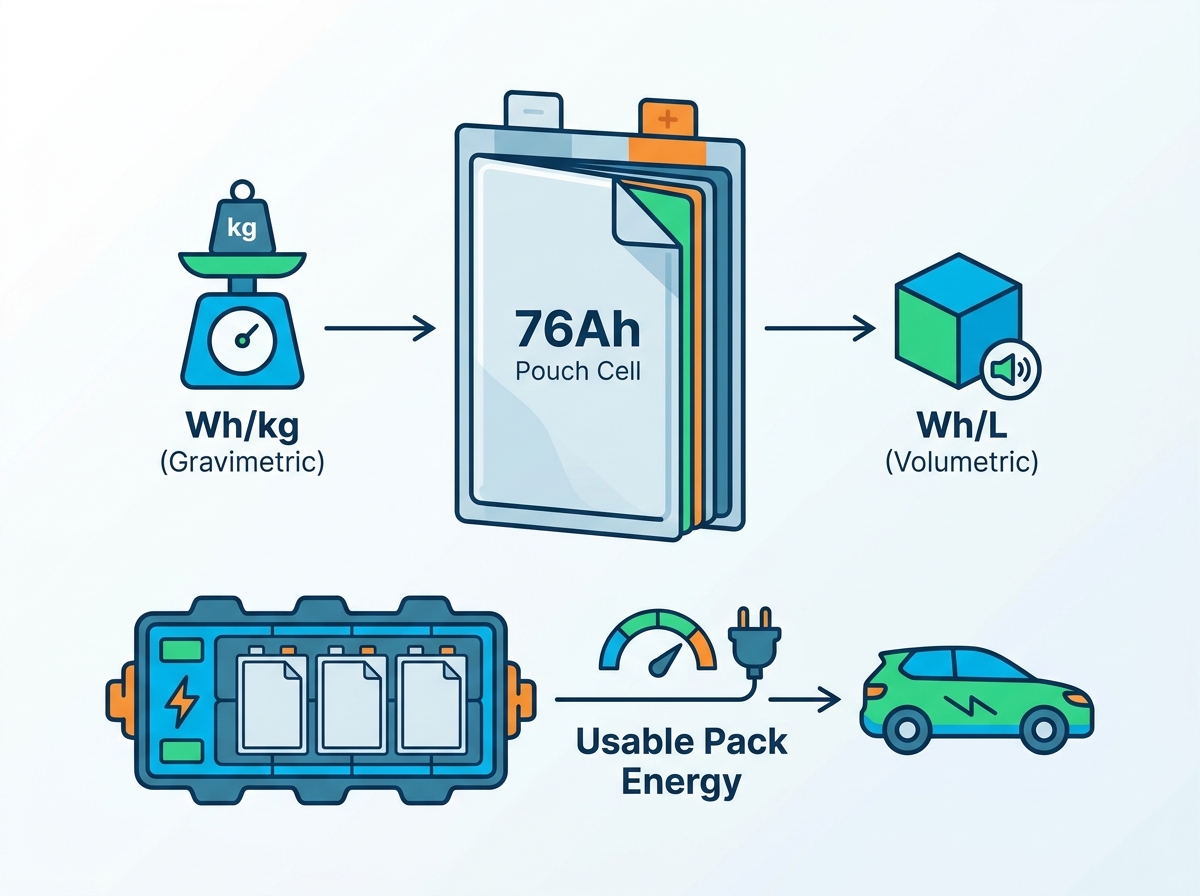
Scaling up the capacity of individual cells changes the engineering math. Analyzing a large-format 76Ah pouch cell reveals an optimized capacity-to-weight ratio. Higher capacity per unit means fewer individual units are required to reach the target pack voltage and energy. This specific 76Ah capacity point serves demanding applications exceptionally well. It provides sustained high-power output without the parasitic weight associated with hundreds of smaller cylindrical cells.
By consolidating energy into a larger footprint, manufacturers increase the ratio of active internal material to inactive external packaging. You get more energy-storing jellyroll and less aluminum-polymer film per amp-hour. This characteristic makes the 76Ah format highly successful in heavy-duty commercial EVs and high-capacity marine energy systems. The focus remains on maximizing continuous discharge capabilities while keeping overall module weight strictly controlled.
Module assembly benefits significantly from larger cell formats. Fewer cells mean fewer points of mechanical failure. You drastically reduce the number of required tab welds. A pack built with 76Ah units requires a fraction of the busbar connections compared to a pack built with 5Ah cylindrical cells. This simplification extends to the Battery Management System. You need fewer voltage sensing wires and fewer temperature probes. The entire wire harness becomes less complex, reducing manufacturing time and lowering the risk of assembly errors.
| Metric (100kWh Pack Example) | 76Ah Pouch Architecture | 5Ah Cylindrical Architecture |
|---|---|---|
| Total Cell Count | ~360 cells | ~5,500 cells |
| Tab Weld Points | ~720 welds | ~11,000 welds |
| BMS Sensing Channels | Low complexity, fewer nodes | High complexity, dense wiring |
| Assembly Complexity | Streamlined, faster throughput | Labor-intensive, high fault risk |
However, this scalability introduces a specific thermal trade-off. Larger cells concentrate heat generation into a smaller number of discrete locations. You cannot rely on ambient air cooling for a massive 76Ah block. This concentration requires more robust, localized thermal interface materials. You must engineer highly efficient heat extraction pathways at the tab connections and across the broad face of the cell to prevent localized hot spots.
Battery format selection dictates the physical layout of your product. Cylindrical cells, like the 21700 or 4680, utilize rigid, standardized steel cans. Prismatic cells use heavy aluminum or steel rectangular housings. These rigid formats offer zero dimensional flexibility. In contrast, the flexible foil packaging allows for customizability in dimensions. Manufacturers can adjust the length and width of the footprint to match specific engineering requirements.
This form factor flexibility allows for maximum utilization of irregular cavity spaces within a product chassis. If an electric vehicle floorpan has an unusual contour, engineers can specify a cell dimension that fills that exact space. You do not lose volumetric efficiency to the empty gaps inherent in packing cylindrical tubes together. This adaptability makes the flexible format ideal for sleek consumer electronics and aerodynamically optimized vehicle frames.
You must frame the core evaluation dimension objectively: flexible foil cells lack inherent structural rigidity. A cylindrical cell acts as its own structural load-bearing member. A prismatic cell can withstand significant external pressure. A foil-packaged cell cannot support mechanical loads. It is vulnerable to bending, puncture, and deformation.
This reality forces a major pack integration trade-off. The weight saved at the individual cell level is sometimes completely offset by the heavy, rigid module frames required to protect them. You must design robust end-plates and tie-rods to apply uniform compression across the cell stack. This uniform compression prevents internal layer delamination during cycling. If you fail to engineer adequate structural support, the cells will degrade rapidly. You must calculate whether the heavy module framing negates the initial gravimetric advantages of the bare cell.
You cannot rely on top-line marketing numbers to determine system performance. Engineers must build an internal calculator model to project real-world usable energy accurately. This framework requires several distinct data inputs.
Follow these steps to calculate true usable energy:
Start with the nominal chemistry values provided by the cell manufacturer.
Multiply the nominal voltage by the amp-hour rating to establish bare-cell Watt-hours.
Subtract the calculated packaging overhead percentages, including the weight and volume of busbars, frames, and enclosures.
Deduct the physical volume required for thermal gaps, compression pads, and active cooling plates.
Account for the weight of the BMS, contactors, and high-voltage cabling.
Apply the Depth of Discharge (DoD) software limits enforced by the BMS.
By inputting these variables, you generate a realistic projection of the final Wh/kg and Wh/L. This calculated number will always be significantly lower than the raw cell data. Using this framework prevents costly late-stage redesigns caused by capacity shortfalls.
You must differentiate between nominal energy and usable energy. Nominal energy is the nameplate capacity printed on the datasheet. Usable energy is the actual amount of power you can extract during daily operation without destroying the battery. Extracting 100% of the stored energy causes severe chemical stress and drastically shortens the operational lifespan.
To extend cycle life, engineers restrict the Depth of Discharge (DoD). A common strategy involves operating the pack strictly between 10% and 90% State of Charge (SoC). This restriction leaves 20% of the nameplate capacity permanently inaccessible. While this strategy ensures the battery lasts for thousands of cycles, it directly reduces the daily usable Wh/kg and Wh/L. You are carrying weight and volume that you cannot actively use for power delivery.
| DoD Strategy | Accessible Capacity | Cycle Life Impact | Usable Energy Density Penalty |
|---|---|---|---|
| 100% DoD (0-100% SoC) | Maximum | Severe degradation, shortest lifespan | 0% penalty |
| 80% DoD (10-90% SoC) | High | Balanced degradation, standard lifespan | 20% penalty |
| 60% DoD (20-80% SoC) | Moderate | Minimal degradation, extended lifespan | 40% penalty |
The Battery Management System acts as the absolute gatekeeper of usable energy. The BMS enforces strict voltage cutoffs to prevent catastrophic failure. It stops discharge before the voltage drops low enough to cause copper dissolution. It halts charging before the voltage rises high enough to trigger lithium plating.
Cell-to-cell variance further complicates usable capacity in large packs. Manufacturing tolerances mean no two cells have the exact same internal resistance or capacity. Over time, these cells drift out of balance. The BMS must perform top-balancing to equalize the voltages. However, the total usable pack energy is ultimately limited by the capacity of the weakest cell block in the series string. When the weakest cell hits the low-voltage cutoff, the BMS shuts down the entire pack, leaving trapped energy in the stronger cells.
Mechanical swelling presents a persistent implementation risk. As lithium ions intercalate into the anode and cathode lattices, the electrodes physically expand. Furthermore, minor side reactions over hundreds of cycles generate internal gases. This combination causes the flexible foil packaging to bulge outward. If left unchecked, this swelling exerts massive pressure on adjacent cells and the module housing.
You must implement specific mitigation strategies to handle this expansion. Engineers utilize precision-engineered compression pads between every cell layer. Polyurethane foam is a standard material choice. These pads absorb the physical expansion while maintaining optimal, uniform pressure across the cell face. The foam must be dense enough to prevent delamination but compressible enough to avoid crushing the internal electrode layers. Proper compression pad selection dictates the target cycle life.
Safety engineering requires addressing the vulnerability of the soft outer layer. The aluminum-polymer film offers minimal resistance to physical puncture. Edge shorting is also a risk if the internal tabs fold or breach the seal. A puncture or internal short circuit can rapidly escalate into thermal runaway, where the cell vents hot gases and ignites.
You must incorporate stringent design features to mitigate these risks and pass mandatory safety certifications. Engineers insert intumescent materials between cell blocks. These materials expand when exposed to high heat, creating a fire-resistant thermal barrier that prevents cell-to-cell propagation. Robust external enclosures are required to prevent physical penetration. Your module design must demonstrate containment of a single-cell failure to achieve compliance with UL 1973, UL 9540A, and UN 38.3 standards. Passing these tests proves the system is safe for transport and deployment.
The flexible foil cell format offers superior theoretical gravimetric energy density compared to rigid alternatives. However, translating that cell-level advantage into a functional, high-performance battery pack requires rigorous engineering. You must manage significant structural overhead to apply uniform compression. You must dedicate volume to thermal management and expansion gaps. The practical application of these cells demands a precise balance between weight reduction goals and mechanical stability requirements.
We recommend this format for projects where weight reduction, portability, and custom spatial configurations are prioritized over inherent cell-level ruggedness. The large-format 76Ah configuration serves as an optimal middle ground. It reduces assembly complexity and minimizes inactive packaging material while delivering sustained high capacity for demanding applications.
To ensure successful integration, execute the following next steps:
Request comprehensive pack-level simulation data from your cell vendors rather than relying on bare-cell datasheets.
Conduct aggressive thermal modeling on your proposed module designs to map heat concentration at the tab connections.
Calculate your specific packaging overhead penalty to establish a realistic baseline for usable Wh/kg and Wh/L.
Initiate low-volume prototyping to validate your compression pad specifications and measure actual mechanical swelling.
Reach out to our engineering team and contact us to review your module design and thermal management strategy.
A: Gravimetric density (Wh/kg) measures energy stored per unit of weight, dictating performance in aerospace and electric vehicles. Volumetric density (Wh/L) measures energy stored per unit of physical space, dictating how much power fits into constrained enclosures. You must balance both metrics to optimize a pack's weight and footprint.
A: The flexible format reduces inactive packaging weight, but the active chemistry dictates the theoretical maximum energy. NMC chemistries typically offer much higher gravimetric density (250-300+ Wh/kg) for high-performance needs. LFP chemistries offer lower density (160-200 Wh/kg) but provide superior thermal stability and longer cycle life.
A: Pack-level density is lower due to the necessary inclusion of inactive components. You must add heavy structural frames, compression plates, busbars, wiring harnesses, and thermal management systems. These components add significant weight and volume without contributing to energy storage, reducing overall density by 20% to 40%.
A: Maximizing Wh/L minimizes the physical footprint of the battery system. In residential solar storage or commercial real estate, floor space is limited and expensive. High volumetric density allows engineers to pack more energy capacity into smaller utility closets or tighter server racks.
A: These cells typically experience a thickness increase of 5% to 10% over their operational lifespan due to electrode expansion and minor gas generation. Engineers must integrate precision compression pads, like polyurethane foam, to absorb this swelling while maintaining uniform pressure across the cell face.
A: The primary advantages include drastically reduced connection points and lower assembly complexity. Fewer cells mean fewer tab welds and a simplified BMS wire harness. It also improves the ratio of active energy-storing material to inactive packaging film, optimizing overall module efficiency.
A: Restricting the DoD by operating only between 10% and 90% capacity preserves the internal chemistry and significantly extends long-term cycle life. However, this restriction means you cannot access the full nameplate capacity, directly reducing the amount of daily usable energy available to the application.


