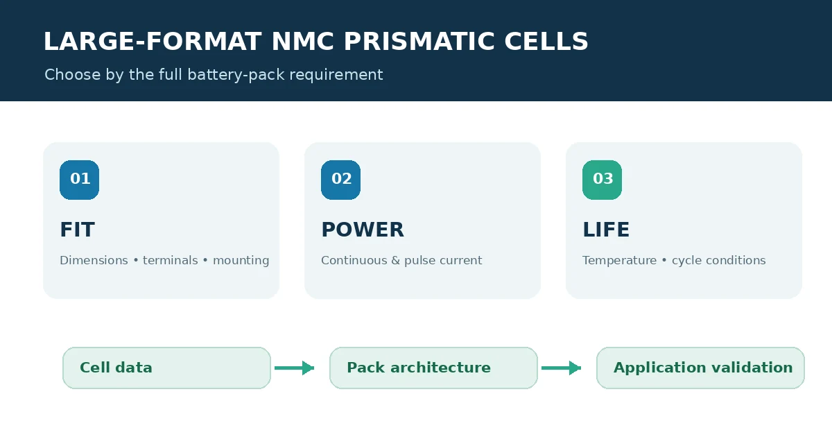
Choosing a large-format NMC prismatic cell for an electric vehicle or battery pack project takes more than selecting the highest amp-hour number. Cell dimensions, voltage limits, current profile, thermal conditions, mechanical support and the evidence behind each specification all affect whether a cell is suitable for the finished system.
Quick answer: Start with the pack envelope and duty cycle, then shortlist cells by verified electrical and mechanical data. Confirm the exact model revision, test conditions and lot documents before comparing ratings or moving to sample validation.
MisenPower’s NCM prismatic cell category includes products across several capacity and size ranges, including listings for EVE and CATL cells. A category listing is a useful starting point; the exact datasheet and offered cell revision must determine the final engineering comparison. Browse NCM prismatic cell options.
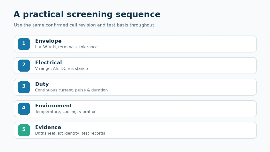
1. Define the battery pack before comparing cells
Write down the system requirements first. A cell that meets the energy target may still fail the installation envelope or the required power profile. For an EV or industrial pack, collect at least:
Target nominal and maximum pack voltage, plus the allowed minimum voltage under load.
Required usable energy and the expected operating window.
Continuous current, peak current, pulse duration and how often pulses occur.
Available cell bay dimensions, service clearances and connection orientation.
Ambient and cell temperature limits, cooling approach, vibration and service life.
Separate must-have limits from preferences. For example, the enclosure dimensions and minimum continuous power may be hard constraints, while a lower mass or a particular nominal capacity may be optimization goals. This prevents an attractive headline rating from distracting from a basic fit or duty-cycle mismatch.
2. Check the mechanical envelope and terminal design
For a prismatic aluminum-case cell, compare the complete drawing, not only the three dimensions shown in a product title. Check length, width and height; terminal type and position; polarity marking; pressure or mounting surfaces; insulation requirements; and the tolerances allowed by the manufacturer. Confirm whether the stated dimensions include terminals, covers or other protrusions.
Also account for the pack structure around the cell: compression or restraint method, busbar access, electrical clearances, cooling plates, service access and manufacturing tolerances. A small difference in terminal position or cell height can change the busbar layout or module spacing. Do not assume that cells with similar capacity or an apparently similar case are mechanically interchangeable.
3. Match voltage, capacity and current to the real duty cycle
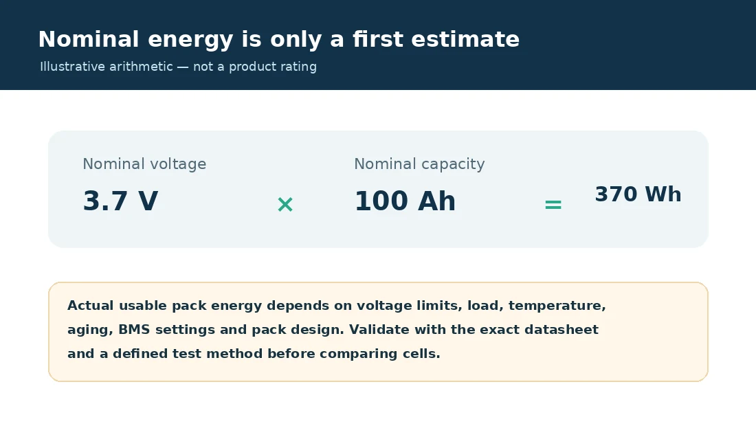
Use the datasheet’s nominal voltage and rated capacity to estimate a first-pass energy figure:
Illustrative example: 3.7 V × 100 Ah = 370 Wh nominal energy per cell. This is arithmetic for explaining the method, not a specification for a listed product or a promise of usable energy.
The pack’s usable energy will differ with the permitted voltage window, discharge rate, temperature, aging, BMS cutoffs and system design. Compare cells only when capacity test conditions are aligned, including temperature, charge procedure, discharge current and cutoff voltage.
Current ratings need the same care. Confirm whether a value is continuous or pulse, the pulse duration and rest interval, state of charge, cell temperature and cooling conditions. A short-duration peak rating cannot be used as a continuous pack rating. The complete pack is also limited by interconnects, fuses, BMS, cooling and enclosure design.
4. Compare cycle life and operating conditions carefully
Cycle-life figures are meaningful only with their test conditions. Before comparing them, check the charge and discharge rates, depth of discharge, temperature, voltage limits and end-of-life criterion. A result at one temperature or current profile should not be presented as a guaranteed lifetime in a different vehicle or battery application.
Review the specified charging limits and thermal range alongside the intended route or operating schedule. A pack used for frequent high-power acceleration, fast charging or operation in a hot environment may need a different balance of power, cooling and service-life targets than a pack used mainly for steady energy delivery.
5. Use a like-for-like comparison table
Build a shortlist from confirmed documentation. Avoid filling missing values with estimates or copying claims from a different model revision.
| Comparison item | What to confirm | Why it matters |
| Identity | Manufacturer, full model code, revision and lot | Prevents mixing data from different variants |
| Geometry | Drawing, dimensions, terminals and tolerances | Determines fit and module interfaces |
| Electrical | Voltage window, capacity, resistance and current limits | Supports energy and power calculations |
| Test basis | Temperature, rates, cutoffs and cycle-life criterion | Makes comparisons meaningful |
| Supply evidence | Datasheet, label images and available lot records | Confirms the offered item matches the review |
6. Validate the shortlist with samples and pack-level checks
Before committing to a production design, verify the cell label and revision, measure the delivered cell dimensions, and test it under the project’s defined charge and discharge profile. Review the mechanical fixture, busbars, insulation, sensing, BMS settings and thermal behavior as a complete system. Sample testing should use a documented procedure and agreed acceptance limits.
Ask the supplier which technical documents are available for the exact model and batch, and clarify any differences between the listing, datasheet and physical sample. Availability of test reports or transport documents can depend on the specific product and shipment, so confirm requirements before ordering.
Common selection mistakes
Choosing by Ah alone without checking voltage, dimensions and power requirements.
Treating pulse current as continuous current or assuming a cell rating is a pack rating.
Comparing cycle-life claims with different temperature, DOD or end-of-life conditions.
Assuming similar case dimensions mean terminal and module compatibility.
Using a category listing in place of the exact model datasheet and lot confirmation.
Frequently asked questions
Are large-format NMC prismatic cells suitable for EV battery packs?
They may be suitable when their verified voltage, capacity, current, dimensions, thermal limits and mechanical requirements match the pack design. Application fit must be evaluated for the exact cell and system.
Does a higher Ah rating always provide a better cell?
No. Higher capacity can increase energy per cell, but it does not by itself establish power capability, service life, fit, weight or total pack performance.
Can two NMC prismatic cells with similar dimensions replace each other?
Not automatically. Verify the full drawing, terminal design, voltage limits, resistance, charge and discharge behavior, thermal characteristics and BMS compatibility before considering a substitution.
What information should I send for a cell recommendation?
Share the application, target voltage and energy, available space, continuous and pulse current with duration, temperature range, quantity, destination and required documents. Drawings or photos of the existing pack can help clarify fit requirements.
Choose from verified project requirements
A sound shortlist starts with the enclosure and duty cycle, then checks each candidate against the same datasheet conditions and validation plan. Explore MisenPower’s NCM prismatic cell category and contact MisenPower’s sales team with your voltage, capacity, dimensions and current profile to discuss suitable options.
Technical note: Product specifications and supply documentation should be confirmed for the exact model, revision and offered lot. The illustrative 3.7 V × 100 Ah calculation is not a product rating. This article does not replace manufacturer documentation or qualified battery-system engineering.